Welcome to the Raspoid website !
The aim of this project is to provide all necessary tools to easily create and develop custom robots in Java, based on a Raspberry Pi® and equiped with multiple types of sensors, motors and actuators.
Among others, this project allows to:
- interact with official LEGO® MINDSTORMS® NXT components via the BrickPi board.
- integrate cheaper and universal components such as an accelerometer, an LCD display, an ultrasound sensor, a thermistor, some servomotors, a camera, some infrared components, and more.
- use the network, to add communications in the developed projects, for instance with the Pushbullet services.
- develop in a more "natural" way, by using the behavioral programming paradigm.
All of this has been developed in a clear architecture, that can easily be extended. In this webpage, you will find all necessary information to install, use and even fork/update/extend our work. The code is shared under the LGPLv3 license. This allows everyone to freely use, distribute and modify our work, even for a commercial use. This license only requires that derived works are licensed under the same license, while works that only use the framework as is do not fall under this restriction.
We hope you will enjoy using this tool as much as we enjoy developing it!
This project is part of a Master thesis presented at UCL/EPL ("Université Catholique de Louvain"/"Ecole Polythechnique de Louvain") in July 2016.
The text of this Master thesis can be downloaded here:
API Quick Start
The simplest solution to start to use this API is to download the Raspoid-all.jar file and import it in your Java project. Each component integrated in the framework has its corresponding example in the com.raspoid.examples package. A Raspberry Pi is the only mandatory part required.
We encourage you to use your usual IDE on your own computer, and use our provided gradle scripts to automatically send your code to the Raspberry Pi, test it and debug through the network. You just need to adapt the IP address in the gradle.properties file, with regard to your configuration. The available commands are the following: gradle.
If you use the Raspoid OS image to deal with your robot, you can you this autodetect python script to detect each Raspoid robot present on your local network:
python autodetect_receiver.py
From the Raspberry Pi, each example can be run with a command like the following:
sudo java -cp raspoid-1.0-all.jar com.raspoid.examples.additionalcomponents.LEDPWMExample
Installation
To use the framework, you just need to download the Raspoid.jar file and import it in your projet. You can also get the complete source code and work from it.
With the Raspoid-all.jar, everything is in place (all dependencies). On the other hand, with the minimal jar, you will need to use a custom version of Pi4J to use the BrickPi part of the API. Indeed, we needed to recompile a custom version of Pi4J to be able to set a custom baud rate. This custom version can be downloaded here: custom Pi4J. And if you need to recompile a new version of Pi4J, here is the procedure to do so: recompile Pi4J.
We also provide you with a complete OS image based on Raspbian. This OS image can be used as is, with everything in place: JARs, OpenCV, etc. You can clone this OS image on an SD card with this procedure. Here is the procedure to recreate the Raspoid OS image.
BrickPi
Motor
The motor is an important piece of the Mindstorms kit. It allows your construction to move or perform some mechanical actions. It has some built-in encoders for counting the steps it performs forward or backward. This allows to control with a good accuracyMotor example
The following example shows how to use a motor with Raspoid. It is first created and bound to a specific port of the BrickPi. Two listeners are attached to this motor. The first one will print the encoder value each time the encoder changes from at least 500 units, while the second one will print rotate each time the motor performed a full rotation. The motor will run during 10 seconds with a power set to 100. It will then stop the motor, reset the encoders and restart the motor. You will notice that the encoders value are updated during the rotation of the motor.Run this example and check the reaction of the motor and the output of you program.
Program
public class MotorsExample {

    public static void main(String[] args) {
        Tools.log("---- Motors Example ----");
        BrickPi.MA = new Motor();
        int range = 500;
        BrickPi.MA.onChange(range, evt -> Tools.log("Encoder value updated (with a delta >= " + range + "): " + evt.getNewValue()));
        BrickPi.MA.onRotate( evt -> Tools.log("Rotate"));
        BrickPi.start();
        Tools.log("Encoders " + BrickPi.MA.getEncoderValue());
        BrickPi.MA.setPower(100);
        Tools.sleepMilliseconds(10000);

        BrickPi.MA.stop();
        BrickPi.MA.resetEncoderValue();

        Tools.log("Encoders " + BrickPi.MA.getEncoderValue());
        BrickPi.MA.setPower(100);
        Tools.sleepMilliseconds(10000);
        Tools.log("stop");
        BrickPi.stop();
    }
}
Sensors
Touch sensor
The touch sensor is the simplest sensor of the Mindstorms kit. It is providing a feedback when it is pressed or released. It can be used for instance to detect that your robot it an object and should stop.Touch sensor example
The Touch sensor is pretty easy to use with Raspoid. First you need to create a touch sensor and attach it to a specific port of the BrickPi. The you can receive pressed or released events by attaching a listener on the Touch sensor. In the following example, the state of the Touch sensor will be print each time it changes. Try to press and release the Touch sensor and check the output in the console.Program
public class TouchSensorExample {

    public static void main(String[] args) {
        Tools.log("---- Touch Sensor Example ----");
        BrickPi.S1 = new TouchSensor();

        BrickPi.S1.onChange((ValueChangeEvent evt)
                -> Tools.log("State changed: old value=" + evt.getOldValue()
                + " new value=" + evt.getNewValue()));

        BrickPi.start();
        Tools.sleepMilliseconds(10000);
        BrickPi.stop();

    }

}
LightOn sensor
The Light sensor allows you robot to "see" the light intensity. It will provide a value for the light intensity detected. When used in On mode, it will light a led and measure the reflected light intensity.LightOn example
The following example demonstrate how to use the LightOn sensor. Like the Touch sensor, it needs to be created and bound to one port of the BrickPi board. A listener is then attached so that it is notified when the intensity changes. Whenever it is changed, the value is printed in the console. Try to move the LightOn sensor and check the output in the console.Program
public class LightOnSensorExample {

    public static void main(String[] args) {
        Tools.log("---- Light Sensor On Example ----");
        BrickPi.S1 = new LightOnSensor();

        int range = 50;
        BrickPi.S1.onChange(range, (ValueChangeEvent evt)
                -> Tools.log("Light intensity updated (with a delta > " + range
                        + "): old value=" + evt.getOldValue() + " new value=" + evt.getNewValue()));

        BrickPi.start();
        Tools.sleepMilliseconds(10000);
        BrickPi.stop();
    }
}
LightOff sensor
The Light sensor allows you robot to "see" the light intensity. It will provide a value for the light intensity detected. When used in Off mode, it will only measure the ambient light intensity.LightOff example
The following example demonstrate how to use the LightOff sensor. Like the Touch sensor, it needs to be created and bound to one port of the BrickPi board. A listener is then attached so that it is notified when the intensity changes. Whenever it is changed, the value is printed in the console. Try to move the LighOff sensor and check the output in the console.Program
public class LightOffSensorExample {

    public static void main(String[] args) {
        Tools.log("---- Light Off Sensor Example ----");
        BrickPi.S1 = new LightOffSensor();

        int range = 50;
        BrickPi.S1.onChange(range, (ValueChangeEvent evt)
                -> Tools.log("Light intensity updated (with a delta > " + range
                        + "): old value=" + evt.getOldValue() + " new value=" + evt.getNewValue()));

        BrickPi.start();
        Tools.sleepMilliseconds(10000);
        BrickPi.stop();
    }
Ultrasonic sensor
The Ultrasonic sensor also allows you robot to "see" by measuring the distance between you robot and an object in front of it. You can use it for detecting objects, movements or simply measure the proximity with an object. (The measure is given in centimeter).Ultrasonic sensor example
In this example, an ultrasonic sensor is created and bound to the BrickPi board. A listener is then attached which will be triggered when a change of 20 centimeter is detected compared to the last detected measure. Whenever the event is triggered, the distance is printed in the console. Try to move the Ultrasonic sensor and check the output in the console.Program
public class UltraSonicSensorExample {

    public static void main(String[] args) {
        Tools.log("---- Ultra Sonic Sensor Example ----");
        BrickPi.S1 = new UltraSonicSensor();

        int range = 20;
        BrickPi.S1.onChange(range, (ValueChangeEvent evt)
                -> Tools.log("Distance updated (with a delta > " + range
                        + "): old value=" + evt.getOldValue() + " new value=" + evt.getNewValue()));

        BrickPi.start();
        Tools.sleepMilliseconds(10000);
        BrickPi.stop();
    }
}
Sound sensor
The Sound sensor allows your robot to hear the sounds around and react to them. It measures the sound pressure level (dB) and will provide a percentage value according to the detected level.Sound sensor example
The following code shows an example of use of the Sound sensor. First the Sound sensor is created and bound to the BrickPi board. Then a listener is attached which will react when a difference of 60% of sound pressure is detected. Whenever the listener is triggered, it will print the sound pressure value in the console. Try to clap in your hands and see the output of this example.Program
public class SoundSensorExample {

    public static void main(String[] args) {
        Tools.log("---- Sound Sensor Example ----");
        BrickPi.S1 = new SoundSensor();

        int range = 60;
        BrickPi.S1.onChange(range, evt -> Tools.log("##Sound sensor value updated (with a delta > " + range
                        + "): old value=" + evt.getOldValue() + " new value=" + evt.getNewValue())
                );

        BrickPi.start();
        Tools.sleepMilliseconds(10000);
        Tools.log("Stop");
        BrickPi.stop();
    }
}
LEDs
The BrickPi contains 2 blue LEDs. These LEDs can easily be controlled, as presented in the example below.Program
public static void main(String[] args) {
        Tools.log("---- Leds Blink Example ----");
        BrickPi.LED1.on();
        BrickPi.LED2.off();
        for(int i = 0; i < 42; i++) {
            BrickPi.LED1.toggle();
            BrickPi.LED2.toggle();
            Tools.sleepMilliseconds(100);
        }
        BrickPi.LED1.off();
        BrickPi.LED2.off();
    }
Additional components
HC-SR04 Ultrasonic
The ultrasonic sensor HCSR04 can be used to evaluate proximity with obstacles, using ultrasound propagation and reflection. Ultrasounds are sound waves with frequencies greater than 20 kHz, which is the upper limit of the human audible range. Our sensor operates at 40 kHz (HC-SR04). The operating principle is based on reflection of sound waves: assuming that the speed of the wave is known, a measure of the time of flight gives easily the distance between them, since both time and distance are proportional.Example
This example takes a new measure in cm from the HC-SR04 each 300 milliseconds, and prints this measure in the standard output. The trig pin is connected to GPIO pin 0 and the echo pin is connected to the GPIO pin 2, as presented in the figure above.Circuit

Ultrasonic sensor (HC-SR04) - Circuit.
Program
public static void main(String[] args) {
    UltrasonicHCSR04 ultrasonicSensor = new UltrasonicHCSR04(GPIOPin.GPIO_00, GPIOPin.GPIO_02);

    while(true) {
        Tools.log(ultrasonicSensor.getDistance() + "cm");
        Tools.sleepMilliseconds(300);
    }
}
MPU6050 Gyroscope & Accelerometer
The MPU6050 is a powerful sensor combining an accelerometer and a gyroscope. It also integrates a DLPF ("Digital Low-Pass Filter"). This DLPF can make fast calculations directly on the chip, reducing the load for the Raspberry Pi. It allows different levels of accuracy to smooth data.Visualizers
Live charts
We provide you with a built-in visualizer that you can easily use, right from this website. The aim of this visualizer is to show data retrieved from an accelerometer, a gyroscope or a complementary filter (this is not limited to the MPU6050 case).
To use this visualizer, you simply need to launch a server like the one presented in raspoid/src/main/com/raspoid/examples/network/MPU6050Accelerometer.java.
This visualizer uses your local network to communicate with your robot. It is then required to use an extension like CORS (Chrome or Firefox) to enable cross-origin resource sharing.
You can get the code of this visualizer here: visualizer.html (bootstrap.min.css and jquery-1.12.0.min.js required).
3D visualizer
This 3D python visualizer uses OpenGL and is based on the work of Andrew Birkett, presented in a post on Bitify (16 November 2013).
Our adapted code is available here: 3DVisualizer.py.
Example
In this example, we simply print the data retrieved from the accelerometer (accelerations & angles calculated from those accelerations), the values from the gyroscope (rates of rotation & angles calculated from those tracked rates of rotation) and the angles calculated through the complementary filter.Circuit
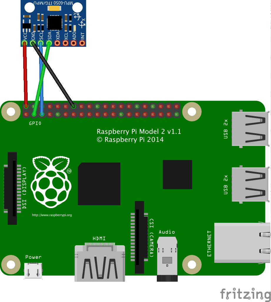
Gyroscope & Accelerometer (MPU6050) - Circuit.
Program
public static void main(String[] args) {
    MPU6050 mpu6050 = new MPU6050();

    while(true) {
        Tools.log("-----------------------------------------------------");

        // Accelerometer angles
        Tools.log("Accelerometer:");
        double[] accelAngles = mpu6050.getAccelAngles();
        Tools.log("\t" + xyzValuesToString(angleToString(accelAngles[0]),
                angleToString(accelAngles[1]), angleToString(accelAngles[2])));

        double[] accelAccelerations = mpu6050.getAccelAccelerations();
        Tools.log("\tAccelerations: " + xyzValuesToString(accelToString(accelAccelerations[0]),
                accelToString(accelAccelerations[1]), accelToString(accelAccelerations[2])));

        // Gyroscope angles
        Tools.log("Gyroscope:");
        double[] gyroAngles = mpu6050.getGyroAngles();
        Tools.log("\t" + xyzValuesToString(angleToString(gyroAngles[0]),
                angleToString(gyroAngles[1]), angleToString(gyroAngles[2])));

        double[] gyroAngularSpeeds = mpu6050.getGyroAngularSpeeds();
        Tools.log("\t" + xyzValuesToString(angularSpeedToString(gyroAngularSpeeds[0]),
                angularSpeedToString(gyroAngularSpeeds[1]), angularSpeedToString(gyroAngularSpeeds[2])));

        // Filtered angles
        Tools.log("Filtered angles:");
        double[] filteredAngles = mpu6050.getFilteredAngles();
        Tools.log("\t" + xyzValuesToString(angleToString(filteredAngles[0]),
                angleToString(filteredAngles[1]), angleToString(filteredAngles[2])));

        Tools.sleepMilliseconds(5);
    }
}
Servomotor
Example
To easily control a servomotor with the Raspoid framework, we implemented a ServoMotor abstract class that can easily be extended for each existing servomotor. The only thing required is to give 6 specific parameters to the servo used. Those parameters can be found on the corresponding datasheets, or one can use our ServoMotorCallibration class to manually determine those coefficients. The setAngle method can then be applied on the servo to set a new position for the rotor. This method will send the corresponding PWM signal for a sufficient duration so that the motor rotates to the new position.Circuit
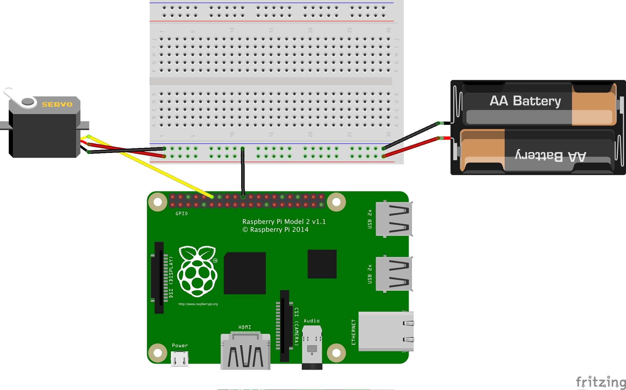
Servomotor (TowerPro MG90S) - Circuit.
Program
public static void main(String[] args) {
    ServoMotor motor;

    // Using a PWM pin
    motor = new TowerProMG90S(PWMPin.PWM1);

    // Using a PCA9685
    //motor = new TowerProMG90S(new PCA9685(), PCA9685Channel.CHANNEL_01);

    double[] angles = {0, 45, 90, 135, 180, 135, 90, 45, 0};

    for(int i = 0; i < angles.length; i++) {
        motor.setAngle(angles[i]);
        Tools.log("position angle: " + motor.getPositionAngle());
        Tools.sleepMilliseconds(1500);
    }
}
Photoresistor
Example
In this example, we use a PCF8591 ADC, a photoresistor and a 1kOhm resistor. This example program simply prints in the standard output each 250 milliseconds the light intensity detected by the photoresistor, in the 0..255 range. One can easily test this code and observe changes of values by varying light intensity on top of the photoresistor.Circuit
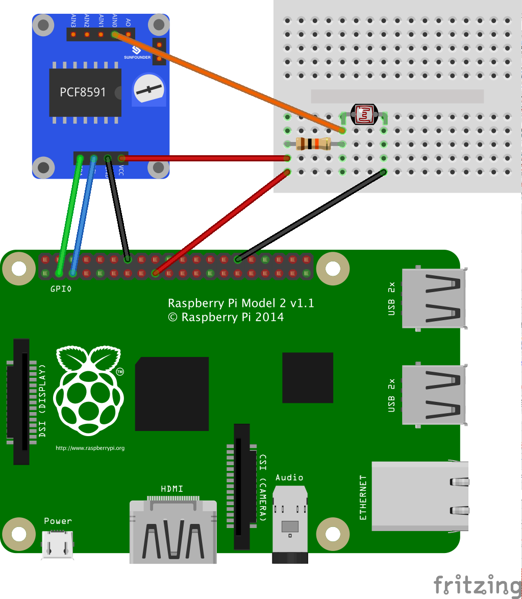
Photoresistor - Circuit.
Program
public static void main(String[] args) {
    Photoresistor photoresistor = new Photoresistor(new PCF8591(), PCF8591InputChannel.CHANNEL_0);

    while(true) {
        Tools.log(photoresistor.getIntensity());
        Tools.sleepMilliseconds(250);
    }
}
LED & LED PWM
A LED is a Light-Emitting Diode. This is a semiconductor that turns electric energy into light energy via a PN junction. Depending on the specifications of the LED, the wavelength of the emitted light can be of any value such as infrared, visible (red, orange, yellow, green, blue, violet), or other.
It is important to not exceed the maximum current allowed through a LED (typically from 10 to 30mA for a basic low power LED) to not destroy it. It is also important to respect the polarity of the diode: we connect the "-" pole to the cathode "-" and therefore the "+" pole to the anode "+".
Example LEDs
In this first example, we use four LEDs of different colors. Each LED is controlled from the Raspberry Pi with the GPIO pins, as presented in the code listing.
Circuit

LED - Circuit.
Program
public static void main(String[] args) {
    LED white = new LED(GPIOPin.GPIO_26);
    LED green = new LED(GPIOPin.GPIO_27);
    LED red = new LED(GPIOPin.GPIO_28);
    LED yellow = new LED(GPIOPin.GPIO_29);

    while (true) {
        white.toggle();
        Tools.sleepMilliseconds(250);
        green.toggle();
        Tools.sleepMilliseconds(250);
        red.toggle();
        Tools.sleepMilliseconds(250);
        yellow.toggle();
        Tools.sleepMilliseconds(250);
    }
}
Example PWM LED
A PWM LED refers to a LED controlled with a PWM signal. With a PWM signal, it is possible to control the energy sent to the LED, and therefore the brightness intensity of the LED.
In this second example, a LED is controlled with a PWM signal, generated from a PCA9685 board. The PCA9685 is controlled from the Raspberry Pi with the I²C protocol. In the code listing, the LED blinks with a dimmer effect.
Circuit
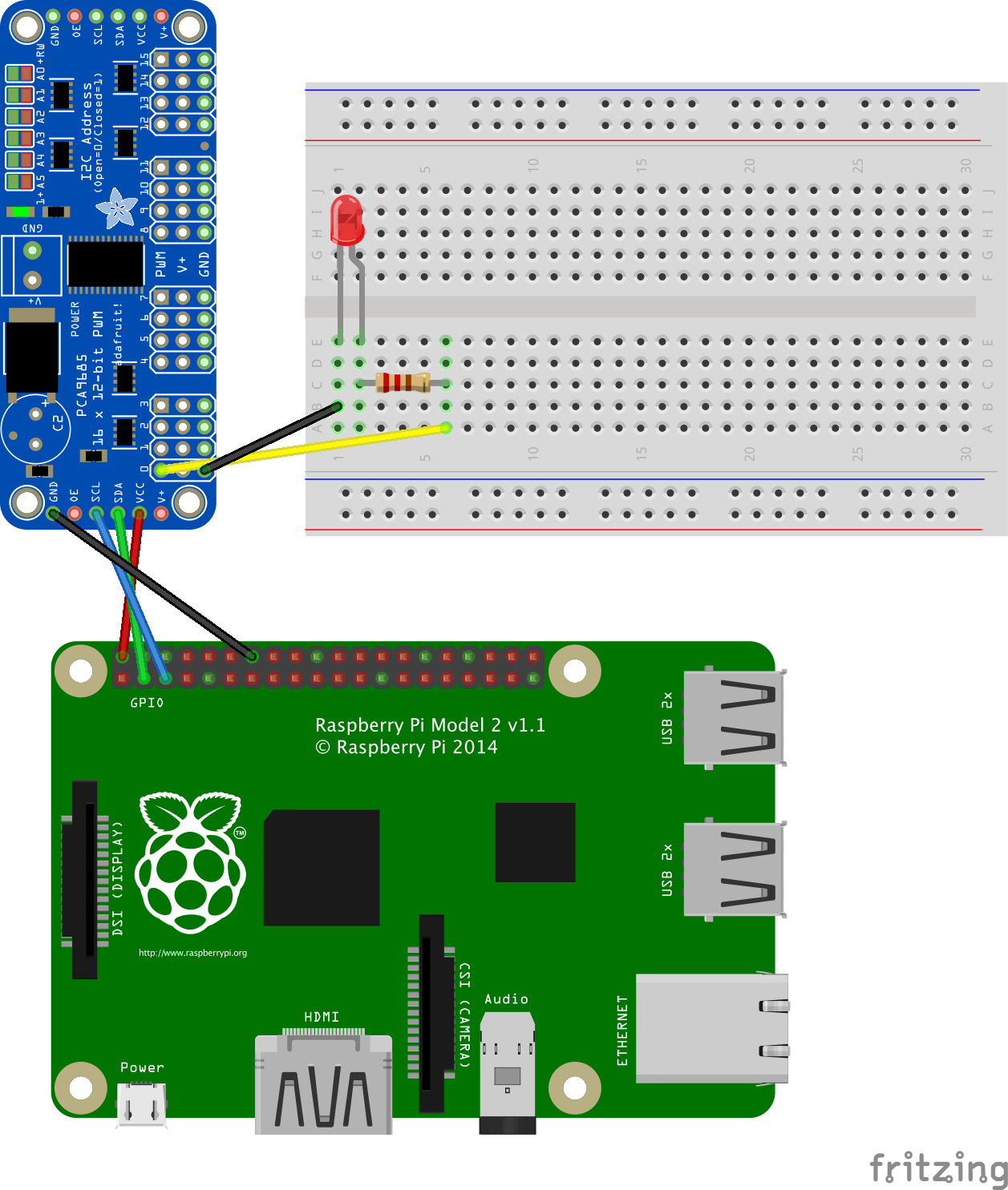
LED PWM - Circuit.
Program
public static void main(String[] args) {
    LEDPWM led = new LEDPWM(new PCA9685(), PCA9685Channel.CHANNEL_00);

    while(true) {
        for(int i=0; i<100; i++) {
            led.setIntensity(i);
            Tools.sleepMilliseconds(5);
        }

        for(int i = 100; i > 0; i--) {
            led.setIntensity(i);
            Tools.sleepMilliseconds(5);
        }
    }
}
Button & Touch switch
A button is a switch which lets the current flow or not. It can be in a direct (the current flows when the button is pressed) or reverse mode (the current flows when the button is released).
A touch switch is a button which state is toggled at each finger touch. First touch: the signal goes high; second touch: the signal goes down; and so on.
Example
In this example, a simple button is connected to the Raspberry Pi. When the button is pressed, an interruption is detected by the Raspberry Pi, and an event is retrieved by the Raspoid program, as presented in the code listing. The same process happens when the button is released.
Circuit
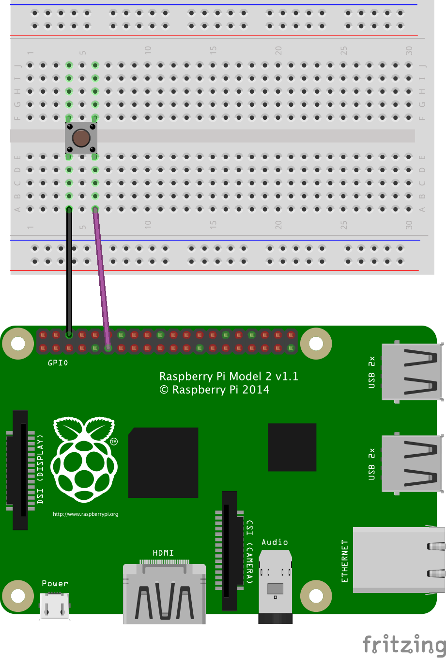
Example of a simple button connected to a GPIO pin. Black: ground; Violet: GPIO 0.
Program
public static void main(String[] args) {
    Button button = new Button(GPIOPin.GPIO_00);

    // Add a listener for button pressed/released events
    button.getGpioPinDigitalInput().addListener((GpioPinListenerDigital)
            (GpioPinDigitalStateChangeEvent event) -> Tools.log(button.isPressed() ? "button pressed" : "button released"));

    Tools.sleepMilliseconds(15000);
}
LCD Display - LCM1602
The LCM1602 is an LCD display of 2 lines and 16 columns (it can display 32 ASCII characters), that can directly be used with the I²C protocol. We implemented a complete wrapper for this component in the Raspoid framework so that it can easily be used.
Example
In this example, the LCD1602 is connected to the LCM1602 (generally, the two components are already welded when purchased). The LCM1602 is connected to the ground, to the 5v power, and to the SDA and SCL pins of the Raspberry Pi.
As presented in the code listing, the LCD displays the current time in the "HH:mm:ss" format, and updates it 4 times per second to avoid delays between the displaying and real time.
Circuit

Example of use of an LCM1602 - Circuit.
Program
public static void main(String[] args) {
    LCM1602 display = new LCM1602();
    display.setDisplay(true, false, false);

    // To execute on exit (clean screen)
    Runtime.getRuntime().addShutdownHook(new Thread(() ->
            display.disableDisplay()));

    display.writeText(0, 0, "Raspoid  Welcome");

    SimpleDateFormat formatter = new SimpleDateFormat("HH:mm:ss");
    while (true) {
        display.writeText(4, 1, formatter.format(new Date()));
        Tools.sleepMilliseconds(250);
    }
}
Joystick
A joystick is mainly composed of two analog outputs. The intensity of the output signal is directly related to the position of the joystick, in the x and y axis (the two analog outputs). From the ADC, we can then retrieve (x,y) coordinates with x and y varying in a range from 0 to 255: (0,0)=bottom left; (126,126)=default position; (255,255)=top right; etc.
The joystick we experimented with with here is an "analog" joystick very similar to those on PlayStation 2 controllers. Positions in x and y are translated from potentiometers (one for each axis). This kind of joystick also acts has a press button. When the button is pressed, the corresponding pin is linked to the ground, and an interruption can be detected.
Example
In this example, a joystick is connected to a PCF8591 (ADC). This ADC is connected to the Raspberry Pi and the I²C protocol is used to retrieve digital values converted from the joystick, and stored on the registers of the PCF8591.
Circuit
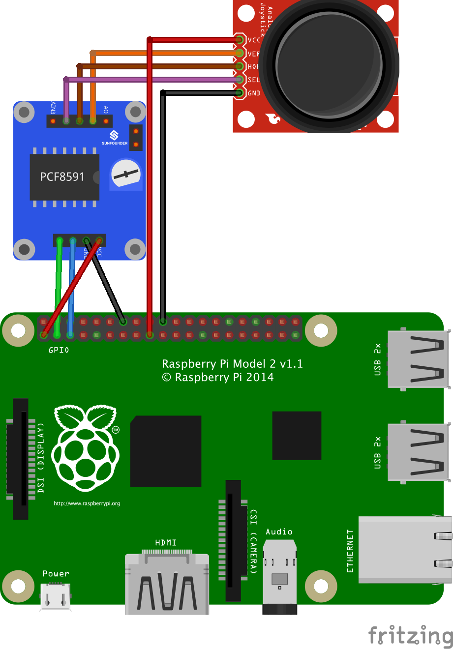
Example of use of a joystick - Circuit.
Program
public static void main(String[] args) {
    Joystick joystick = new Joystick(new PCF8591(), PCF8591InputChannel.CHANNEL_0, PCF8591InputChannel.CHANNEL_1, PCF8591InputChannel.CHANNEL_2);

    while(true) {
        Tools.log(joystick.getPosition()); // press-down, up/down, left/right, home
        Tools.sleepMilliseconds(250);
    }
}
Rotary Encoder
A rotary encoder is used here to detect the orientation of a shaft. Two digital input pins are used by this module. The signals on those two pins are analyzed and combined to deduce the direction of new rotations. We then use a counter to represent the orientation: when turned to the right, the counter is incremented; when turned to the left, it is decremented.
Example
In the following example, a rotary encoder is connected to the Raspberry Pi by using three GPIO pins. Digital values read from those pins are combined to determine the direction of new rotations. Internally, a counter is used to represent the position of the shaft of the rotary encoder. When turning to the right or to the left, the updated value of the counter will be printed in the standard output.
Circuit

Example of use of a rotary encoder - Circuit.
Program
public static void main(String[] args) {
    RotaryEncoder rotaryEncoder = new RotaryEncoder(GPIOPin.GPIO_27, GPIOPin.GPIO_28, GPIOPin.GPIO_29);

    rotaryEncoder.getGpioPinDigitalInput().addListener((GpioPinListenerDigital)
            (GpioPinDigitalStateChangeEvent event) -> Tools.log(rotaryEncoder.isPressed() ? "rotary pressed" : "rotary released"));

    int previousCounterValue = rotaryEncoder.getCounterValue();
    while(true) {
        rotaryEncoder.getEncoderTurn();
        if(previousCounterValue != rotaryEncoder.getCounterValue()) {
            Tools.log(rotaryEncoder.getCounterValue());
            previousCounterValue = rotaryEncoder.getCounterValue();
        }
    }
}
Temperature
A thermistor is made of semiconductor materials, for which the resistance varies significantly with ambient temperature. It can mainly be used to detect variations of the ambient temperature.
Example
In this example, a thermistor is connected to a PCF8591 (ADC). This ADC is connected to the Raspberry Pi and the I²C protocol is used to read values converted from the thermistor and stored in the registers of the PCF8591.
Circuit

Example of use of thermistor - Circuit.
Program
public static void main(String[] args) {
    Thermistor thermistor = new ThermistorNTCLE203E3103SB0(new PCF8591(), PCF8591InputChannel.CHANNEL_0);

    while(true) {
        Tools.log(thermistor.getTemperature());
        Tools.sleepMilliseconds(500);
    }
}
BMP180 Barometer
The barometer BMP180 is a digital barometric pressure sensor. It can be used to measure air pressure and temperature. The pressure varying with the altitude, this sensor can also be used as an altimeter.
Example
In this example, a BMP180 is connected to the Raspberry Pi and the I²C protocol is used to communicate with the sensor and retrieve data from the registers of the component.
Circuit
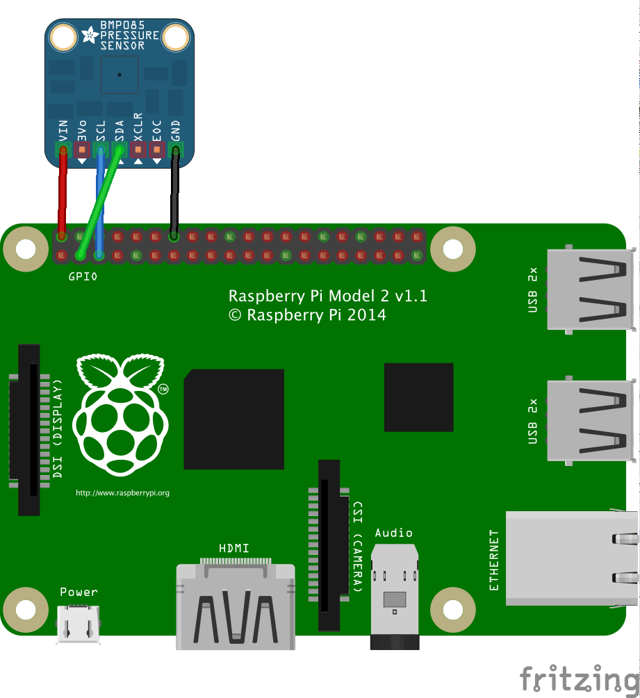
Example of use of a BMP180 - Circuit.
Program
public static void main(String[] args) {
    BarometerBMP180 barometer = new BarometerBMP180();

    while(true) {
        Tools.log(
            "Air pressure: " + barometer.readUncompensatedPressure() + " " +
            "True air pressure: " + barometer.calculateTruePressure() + " Pa\n" +
            "Temperature: " + barometer.readUncompensatedTemperature() + " " +
            "True temperature: " + barometer.calculateTrueTemperature() + "°C\n" +
            "Altitude: " + barometer.calculateAbsoluteAltitude() + "m",
            Tools.Color.ANSI_GREEN);
        Tools.sleepMilliseconds(1000);
    }
}
IR Receiver
Our implementation of the infrared transmitter/receiver allows the user to easily control its robot with infrared signals.
The infrared receiver has been designed here to detect infrared signals sent from a media remote (for instance). The implementation of an infrared media remote using an infrared-LED can be made with the IR transmitter previously presented.
Example
In the first part of this example, when an infrared signal is detected by the IR receiver, if the signal is correctly decoded, the result is printed in the standard output.
In the second part of this example, an infrared signal is sent through the infrared LED. This signal is the same as the signal sent from the infrared media remote sold by Sunfounder, when button 1 is pressed.
Circuit
Example of use of an IR receiver (on the left) and an IR transmitter (on the right) - Circuit.
Program
public static void main(String[] args) {
    IRReceiverOS1838B irReceiver = new IRReceiverOS1838B(GPIOPin.GPIO_00);

    while(true) {
        IRSignal newSignal = irReceiver.detectSignal();

        IRSignal signalDecoded = irReceiver.decodeIRSignal(new IRProtocolSunfounderMediaRemote(), newSignal);
        if(signalDecoded != null)
            Tools.log("New signal received and decoded: " + signalDecoded.getName());
        else
            Tools.log("New signal received but NOT decoded: " + newSignal);
    }
}
IR Transmitter
Our implementation of the infrared transmitter/receiver allows the user to easily control its robot with infrared signals.
An infrared transmitter is an infrared LED that should be connected to a Raspberry Pi's PWM pin (the frequency from the PCA9685 is not enough for infrared signals). Infrared signals can then be sent and detected with the receiver presented here after.
Example
In the first part of this example, when an infrared signal is detected by the IR receiver, if the signal is correctly decoded, the result is printed in the standard output.
In the second part of this example, an infrared signal is sent through the infrared LED. This signal is the same as the signal sent from the infrared media remote sold by Sunfounder, when button 1 is pressed.
Circuit
Example of use of an IR receiver (on the left) and an IR transmitter (on the right) - Circuit.
Program
public static void main(String[] args) {
    IRTransmitter transmitter = new IRTransmitter(PWMPin.PWM0);
    transmitter.transmitSignal(IRProtocolSunfounderMediaRemote.button1);
    Tools.log("IR signal sent");
}
Accelerometer - ADXL345
The accelerometer ADXL345 is a cheap accelerometer that can be used to retrieve accelerations for x, y and z axes.
Example
In this example, we use the I²C protocol to control the accelerometer, and to retrieve values corresponding to (x, y, z) coordinates of the last measured acceleration vector.
Circuit
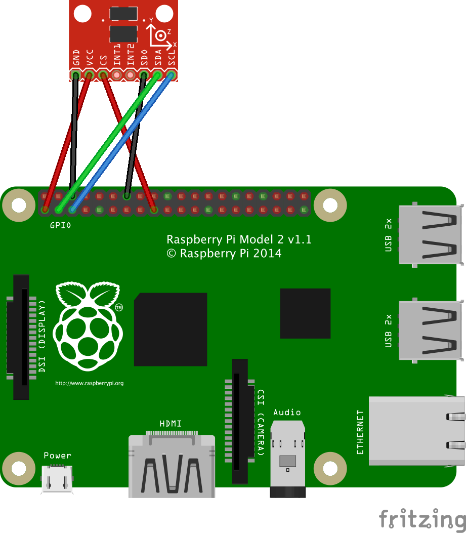
Example of use of an ADXL345 accelerometer - Circuit.
Program
public static void main(String[] args) {
    AccelerometerADXL345 accel = new AccelerometerADXL345();

    while(true) {
        Tools.log("Acceleration: " + accel.getGAcceleration()); // {x, y, z} vector
        Tools.log("Pitch angle: " + accel.getPitchAngle() + "°");
        Tools.sleepMilliseconds(250);
    }
}
LM386 Sound
A sound sensor is composed of a simple microphone and is able to detect ambient sound intensity by converting audio signals to analog electrical signals.
Example
In this example, the sound sensor is used with a PCF8591 to convert the analog signal to a digital one. The PCF8591 is connected to the Raspberry Pi and the I²C protocol is used to retrieve those digital values.
Circuit

Example of use of a sound sensor - Circuit.
Program
public static void main(String[] args) {
    SoundSensor soundSensor = new SoundSensor(new PCF8591(), PCF8591InputChannel.CHANNEL_0);

    while(true) {
        Tools.log(soundSensor.getIntensity());
        Tools.sleepMilliseconds(25);
    }
}
Active Buzzer
An active buzzer has a built-in oscillating source. It will produce a sound at a specific frequency, as long as it is electrified.
Example
In this example, we show the use of a buzzer. This buzzer can be active or passive. The only difference in the circuit is the pin used on the Raspberry Pi. This pin must be a PWM pin for a passive buzzer (to play specific tones by adapting frequencies of the PWM signal), while it must be a classical GPIO pin for an active buzzer (it produces sound only when electrified).
In this example, the active buzzer will loop between beep and silence every 500 milliseconds.
Circuit
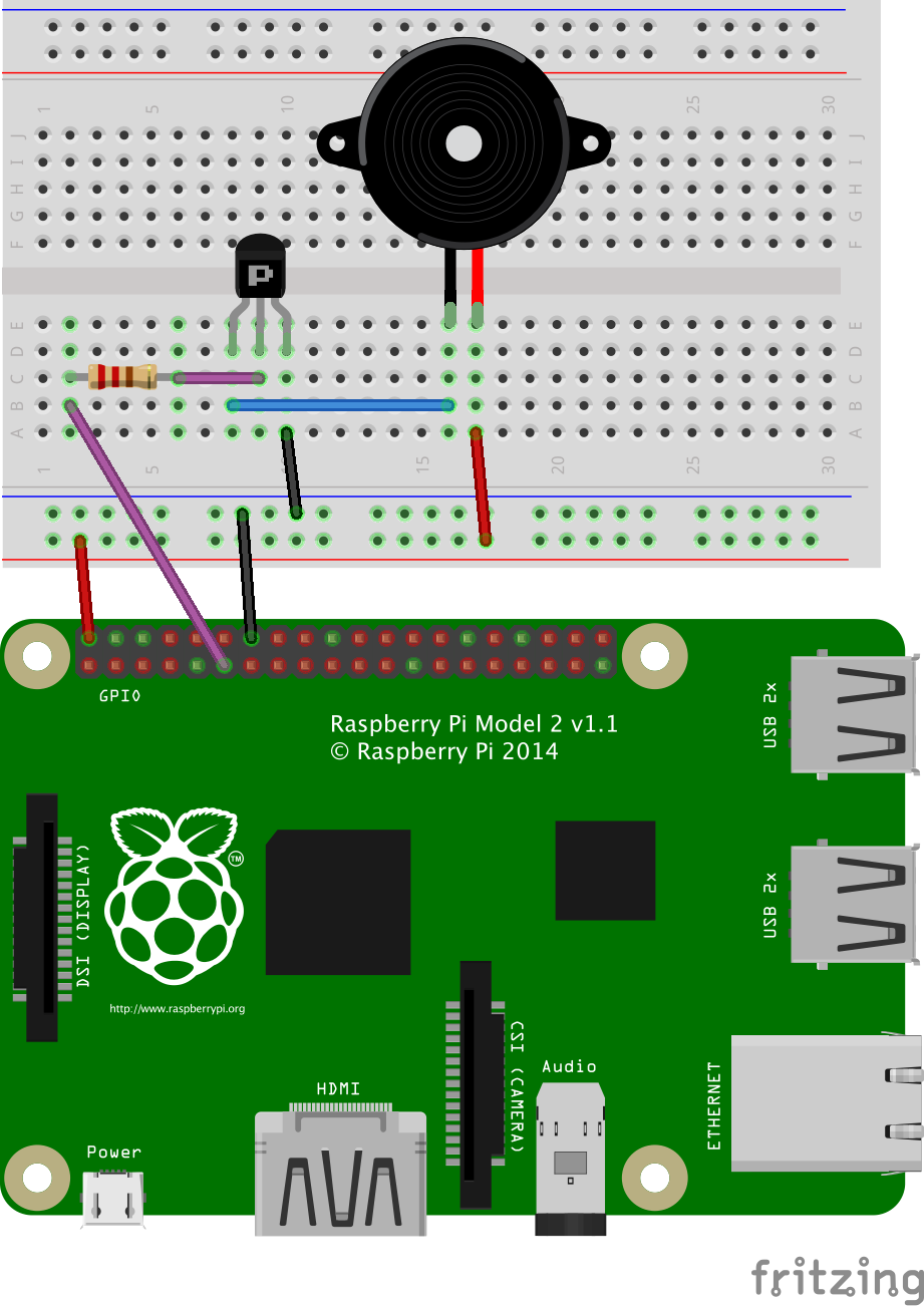
Example of use of an active buzzer - Circuit.
Program
public static void main(String[] args) {
    ActiveBuzzer buzzer = new ActiveBuzzer(GPIOPin.GPIO_00, true);
    while(true)
        buzzer.beep(500);
}
Passive Buzzer
A passive buzzer can be used to control the frequency of the generated sounds. Our implementation allows the user to play music by specifying base tones, octaves and notes duration.
Example
In this example, we show the use of a buzzer. This buzzer can be active or passive. The only difference in the circuit is the pin used on the Raspberry Pi. This pin must be a PWM pin for a passive buzzer (to play specific tones by adapting frequencies of the PWM signal), while it must be a classical GPIO pin for an active buzzer (it produces sound only when electrified).
In this example, the passive buzzer will play each note of the scale "do re mi fa sol la si", and loop through octaves from 0 to 7 (500 milliseconds per tone).
Circuit
xample of use of a passive buzzer - Circuit.
Program
public static void main(String[] args) {
    int timePerNote = 500; // ms
    PassiveBuzzer buzzer = new PassiveBuzzer(PWMPin.PWM1);

    for(int i=0; i <= 7; i++) {
        buzzer.playNote(BaseNote.DO_0, i, timePerNote);
        buzzer.playNote(BaseNote.RE_0, i, timePerNote);
        buzzer.playNote(BaseNote.MI_0, i, timePerNote);
        buzzer.playNote(BaseNote.FA_0, i, timePerNote);
        buzzer.playNote(BaseNote.SOL_0, i, timePerNote);
        buzzer.playNote(BaseNote.LA_0, i, timePerNote);
        buzzer.playNote(BaseNote.SI_0, i, timePerNote);
    }
}
Tracking Sensor - TCRT5000
A tracking sensor uses the same principle as the infrared obstacle avoidance module. An infrared signal is emitted, and the reflected signal is received by the detector part of the module. The particularity used here, is that black color will not reflect infrared signals. Thus, the sensor can be oriented towards the ground, and used to track a black line.
Example
In this example, when the detected color switches between white and black, an event is triggered and the new detected color is printed in the standard output.
Circuit
Example of use of a tracking sensor - Circuit.
Program
public static void main(String[] args) {
    TrackingSensor trackingSensor = new TrackingSensor(GPIOPin.GPIO_00);

    trackingSensor.getGpioPinDigitalInput().addListener((GpioPinListenerDigital)
            (GpioPinDigitalStateChangeEvent event) ->
    Tools.log("Color: " + (event.getState().isLow() ? "white" : "black")));
}
IR Obstacle Avoidance Module
The infrared obstacle avoidance module is a little chip composed of an infrared emitter and an infrared receiver. It uses the infrared reflection principle to detect obstacles: when there is no object ahead of the emitter, the receiver cannot detect signals; when there is an obstacle, the infrared light is reflected and is then detected by the receiver (it detects obstacles in a 0-7 cm range). The module presented here is sold by Sounfounder.
Example
In this example, an event is triggered when an obstacle is detected, or when the obstacle has disappeared. A message is simply printed in the standard output each time the status changes (obstacle detected / no obstacle).
Circuit
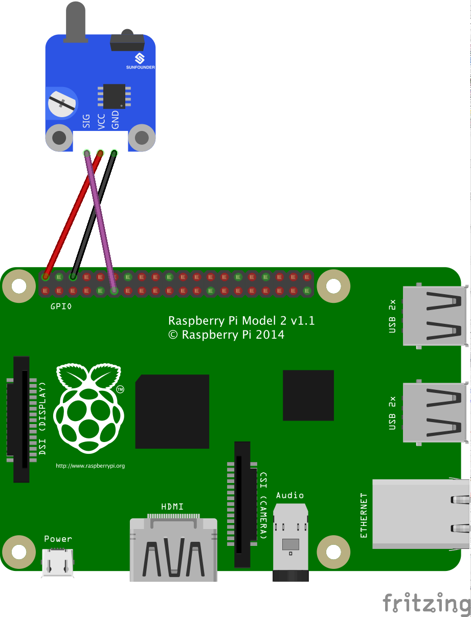
Example of use of an obstacle avoidance module - Circuit.
Program
public static void main(String[] args) {
    IRObstacleAvoidanceModule obstacleAvoidanceModule = new IRObstacleAvoidanceModule(GPIOPin.GPIO_00);

    obstacleAvoidanceModule.getGpioPinDigitalInput().addListener((GpioPinListenerDigital)
            (GpioPinDigitalStateChangeEvent event) -> Tools.log(event.getState().isLow() ? "obstacle detected" : "no obstacle"));

    Tools.sleepMilliseconds(15000);
}
Camera Pi
The camera module distributed by the Raspberry Pi Foundation is able to take pictures and videos. The Foundation distributes two versions of the camera module: the "regular" and the "Pi NoIR". The Pi NoIR camera module works exactly as the regular one, with one difference: no infrared filter is used. This allows to conceive projects to "see in the dark" (while pictures and videos taken by daylight will look rather curious!).
In the Raspoid framework, we implemented a complete wrapper for the raspistill and raspivid command line tools distributed by the Raspberry Pi Foundation. With our java wrappers, one can easily launch a preview window on a HDMI or PCB display directly connected to the Raspberry Pi, take still photos and videos. We also developed a solution to easily stream live video from the Raspberry Pi through the network with GStreamer, and we compiled a complete version of OpenCV (Open-source Computer Vision) to be fully compatible with the Raspberry Pi (rather tricky). All the required tools and components are installed in our Raspoid OS image.
Example
We will provide here one simple example for each category of features offered by the framework. It's impossible to list all the available methods here. We then recommend the user to look at the complete API to see all the offered capabilities..
The methods developed for this part of the framework are available in a static way. If the user needs to apply some specific modification on the image from the camera (vertical/horizontal split, width, height, opacity, resolution, exposure, etc.), we offer four configuration abstractions that can easily be used and then passed in argument of static methods. The CameraControlOptions refers to settings common to all images coming from the camera module: contrast, brightness, saturation, etc. The PreviewConfig, PictureConfig and VideoConfig entities are specific to the use of the corresponding features: width, height, output file name, quality, etc. Indeed, the range of available values for some options can be different for a picture, a preview or a video.
Circuit
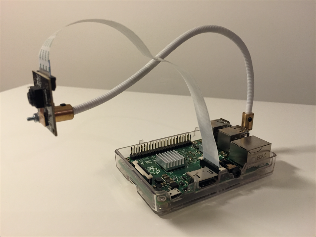
Camera Pi connected to a Raspberry Pi 2.
Program
public static void main(String[] args) {
    // PREVIEW
    CameraPi.preview(5000);

    // PICTURES
    Picture picture1 = CameraPi.takePicture();
    Tools.log("New picture: " + picture1.getFilePath());

    PictureConfig pictureConfig = new PictureConfig("snowy_scenery", 2592, 1944);
    pictureConfig.setExposureMode(ExposureMode.SNOW);
    Picture picture2 = CameraPi.takePicture(pictureConfig);
    Tools.log("New picture: " + picture2.getFilePath());

    // VIDEOS
    Video video = CameraPi.takeVideo(5000);
    Tools.log("New video: " + video.getFilePath());
    String convertedVideoFilePath = video.convertToMP4();
    Tools.log("Converted file: " + convertedVideoFilePath);

    // STREAMING
    CameraPi.startGStreamerServer(NetworkUtilities.getIpAddresses().get(0),
            NetworkUtilities.getAvailablePort(), 640, 360, true, true, 2500000, true, false);

    // OPENCV
    // Load the OpenCV native library.
    System.loadLibrary(Core.NATIVE_LIBRARY_NAME);

    // Take a picture with the camera pi
    String pictureId = new SimpleDateFormat("yyyy_MM_dd_HH_mm_ss").format(new Date());
    PictureConfig pictureConfig = new PictureConfig("capture_" + pictureId, 640, 480);
    pictureConfig.setVerticalFlip(true);
    String filePath = CameraPi.takePicture(pictureConfig).getFilePath();

    // Look for faces
    Mat image = Highgui.imread(filePath);
    Rect[] faces = FaceDetector.detectFaces(image);
    Tools.log(String.format("%s faces detected", faces.length));

    // Create a new picture, with detected faces
    FaceDetector.surroundFaces(image, faces, "output_" + pictureId + ".jpg");
}
Network capabilities
Communications is an important aspect in robotics. It should be possible to control a robot through the network or to receive information from it, in a synchronous or asynchronous manner. Our architecture for the networking part of the framework is based on the use of a router. The aim of this router is to bring a collection of routes, and to map those routes to some specific logic. The router is at the core of the Raspoid networking functionalities and can be used with any kind of server. A server is like an additional layer implemented on top of the router. We implemented a simple socket server allowing raw or HTTP requests, a message-like socket server, and a Pushbullet server to be able to use the Pushbullet services.
The use of the networking part of the framework is as pretty simple, as shown in the following code listing.
public static void main(String[] args) {
    // A simple router...
    Router router = new Router();

    // 2 kinds of routes:
    // without parameters
    Thermistor thermistor = new ThermistorNTCLE203E3103SB0(new PCF8591(), PCF8591InputChannel.CHANNEL_0);
    router.addRoute("temperature", () -> thermistor.getTemperature() + "°C");

    // with parameters
    PassiveBuzzer buzzer = new PassiveBuzzer(PWMPin.PWM0);
    router.addRouteWithParams("play", 2, inputArgs -> {
        buzzer.playTone(Double.valueOf(inputArgs[0]),  Integer.valueOf(inputArgs[1]));
        return "Tone played.";
    });

    // 3 kinds of servers to send requests to and to receive responses from
    SocketServer socketServer = new SocketServer(5, 80, router);
    socketServer.start();
    MessageLikeSocketServer messageLikeSocketServer = new MessageLikeSocketServer(router);
    messageLikeSocketServer.start();
    Pushbullet pushbullet = new Pushbullet("YOUR_PUSHBULLET_ACCESS_TOKEN", "Raspoid - Example", router);
}
Router
A router is primarily a collection of routes together with their corresponding logic executed when the route is called. Two kinds of routes can be added to a router: routes with or without parameters.
Socket server
A socket is used by a node (a client or a server) to control incoming and outgoing flows of data on the network. Each socket is bound to a specific (IP address, port number) pair. In our implementation, we use these sockets with the TCP protocol. We implemented our socket server to allow the user to apply simple raw requests or more complex HTTP/1.1 GET requests. When HTTP is not required, a simple socket client can be implemented by the user to send requests to the server. In that case, the packets sent to the server must only contain the signature of the route corresponding to the request to apply on the server.
When HTTP is used, it is automatically handled by the server, by analyzing the first bytes of the received data for each request. Indeed, each HTTP/1.1 GET request starts with a "GET" string. The server then replies with a response starting with an "HTTP/1.1" header. We decided to handle HTTP/1.1 GET requests to allow a user to simply use its web browser to send requests to its robot.
Message-like socket server
The message-like socket server extends the previously presented socket server. The need for a message-like socket server is specific to some use cases. When two nodes communicate by sending TCP segments, there is no guarantee that when sending a 100 bytes chunk of data, it will be delivered as a unique 100 bytes chunk on the receiver side. There is no way for the receiver to detect the bounds of the data to decode. A bytes chunk sent could be received in several TCP segments, or several data chunks could be merged in a single TCP segment. It is therefore required to deal with these data bounds to ensure reading as many bytes on the receiver side than the number of bytes in the chunk sent. This is done with the implementation of a small protocol on top of TCP.
Our protocol is pretty simple. Each message has a specific format as shown in the following figure. The first four bytes are used to define the size of the payload (in bytes). The payload size is defined as a Java primitive int value (32-bit signed two's complement integer, which has a minimum value of -2^31 and a maximum value of 2^31-1. Negative values do not make sense and are not used.). The payload must be encoded using the UTF-8 charset. When a receiver detects a new packet, it knows the length of a message and can be sure to read the required number of bytes before delivering them.
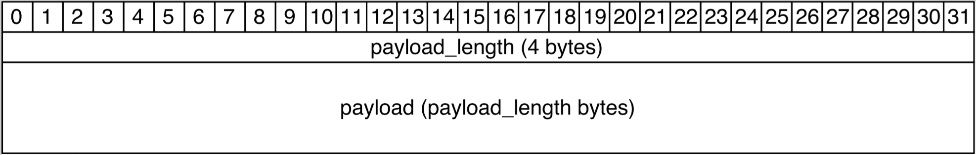
Message-like socket server - Message format.
When using our message-like socket server, it is required to implement the client side to deal with our protocol. As an example, in the following code listing, we implemented a simple method sending a new message from the remote joystick, to one of our robots. The robot has a camera support which can be rotated around x and y axes.
public static void main(String[] args) {
private void updateCameraSupportOrientation(int x, int y) {
    String request = "update_camera_support_orientation/" + x + "/" + y;
    try {
        byte[] message = request.getBytes("UTF-8");
        outputStream.writeInt(message.length);
        outputStream.write(message);
        outputStream.flush();
    } catch (IOException e) {
        throw new RaspoidException("Problem when sending new Joystick update: (request) " + request, e);
    }
}
Pushbullet
Pushbullet was created in 2013 in San Francisco by Andre von Houck, Ryan Oldenburg and Chris Hesse. The aim of Pushbullet is to allow a user to efficiently share information, files and links between his devices: computers, smartphones, tablets, etc. It also allows to share information and messages with other users.
With our implementation, it is possible to use Pushbullet services to:
- create a new Pushbullet device corresponding to a robot, and add this device to the list of devices of a user,
- use this Pushbullet device to send messages/requests to a Raspoid robot from any other Pushbullet device (smartphone, tablet, browser extension, etc.),
- receive responses to messages sent to a Raspoid robot,
- receive notifications sent by a Rasoid robot, on all other devices of a user.
To use the official Pushbullet API, an access token is required. This access token grants full access to the user's account. It is important that this token remains secret. It can easily be created from the Pushbullet user's dashboard (Pushbullet.com > Settings > Access Tokens > Create Access Token}.
public static void main(String[] args) {
    Pushbullet pushbullet = new Pushbullet("YOUR_PUSHBULLET_ACCESS_TOKEN", "Raspoid - Example", new Router());
    pushbullet.sendNewPush("Hello !", "Hello world !");
}
Behavioural programming
Behavioral programming is a paradigm that can be used to program robots in a natural way by specifying behaviors. A behavior implements the operation of a robot when a specific condition is met. With this paradigm, the global behavior of the robot is governed by the combined set of behaviors implemented. All behaviors are independent and can easily be added or removed from the system. This helps to have a very incremental approach when developing the control program of a robot. One can specify at first the most general behaviors of the robot, and then add behaviors handling some more specific situations, thus refining for instance a reaction in response to an edge case.
With Raspoid, only one behavior is executed at a time according to its priority. An arbitrator is in charge of continually traversing the list of behaviors, and to execute the claiming behavior with the highest priority.
In practice, here is how to use the behavioral programming with Raspoid. Two interfaces define the methods needed for an arbitrator and for a behavior. Each one of them has an implementation which is called respectively SimpleArbitrator and SimpleBehavior. The SimpleArbitrator can be used as is, whereas the SimpleBehavior needs to be overridden to add some effective behavior. The arbitrator comprises three methods to start, stop and re-launch immediately an arbitration process. The behavior has more methods needing to be overridden, and deserves more explanations:
- claimControl is the first method to override when implementing a behavior. It is called by the arbitrator when traversing the list of behaviors to check if a behavior wants to be in control of the robot.
- gainControl is the entry point of the behavior when it has been selected by the arbitrator to execute. This is the place where the behavior will perform its logic to control the robot.
- yieldControl is called by the arbitrator when it asks the behavior to stop its execution. The arbitrator is polite, therefore it will not kill the current behavior brutally. However when the yieldControl method has been called, the behavior should ensure that the gainControl method stops as fast as possible. Therefore in the logic of the behavior, it should regularly check if the yieldControl method has been called.
- getPriority as its name suggests, returns the priority assigned to the behavior. This value will be used to sort the behaviors and break the tie when several behaviors are claiming control.
- reset is a utility method used to reset the state of the behavior before it gains control. The behavior can thus do some cleanup from older execution, or simply initialize what is needed before gaining control of the system.
As an example of how the behavioral programming could be used, here is a scenario involving two behaviors. The first behavior named MotorBehavior has the lowest priority, and always claims control. Its purpose is to constantly make the motor turn with a specific speed. The second behavior called SoundBehavior has a higher priority but will only claim control when a clap in the hand has been detected. When it gains control it simply executes an anonymous function reversing the direction in which the motor is turning. When the MotorBehavior takes the control back, it will make the motor turn in the reverse direction. The complete example can be find in the "com.raspoid.examples.behavioral" package.
public static void main(String[] args) {
        SimpleArbitrator sa = new SimpleArbitrator();
        MotorBehavior motorBehavior = new MotorBehavior();
        sa.addBehavior(motorBehavior);
        sa.addBehavior(new SoundBehavior(() ->
            motorBehavior.setPower(-motorBehavior.getPower())
        ));
        BrickPi.start();
        sa.start();
        Tools.sleepMilliseconds(30000);
        sa.stop();
        BrickPi.stop();
}
Examples
Proof of concept
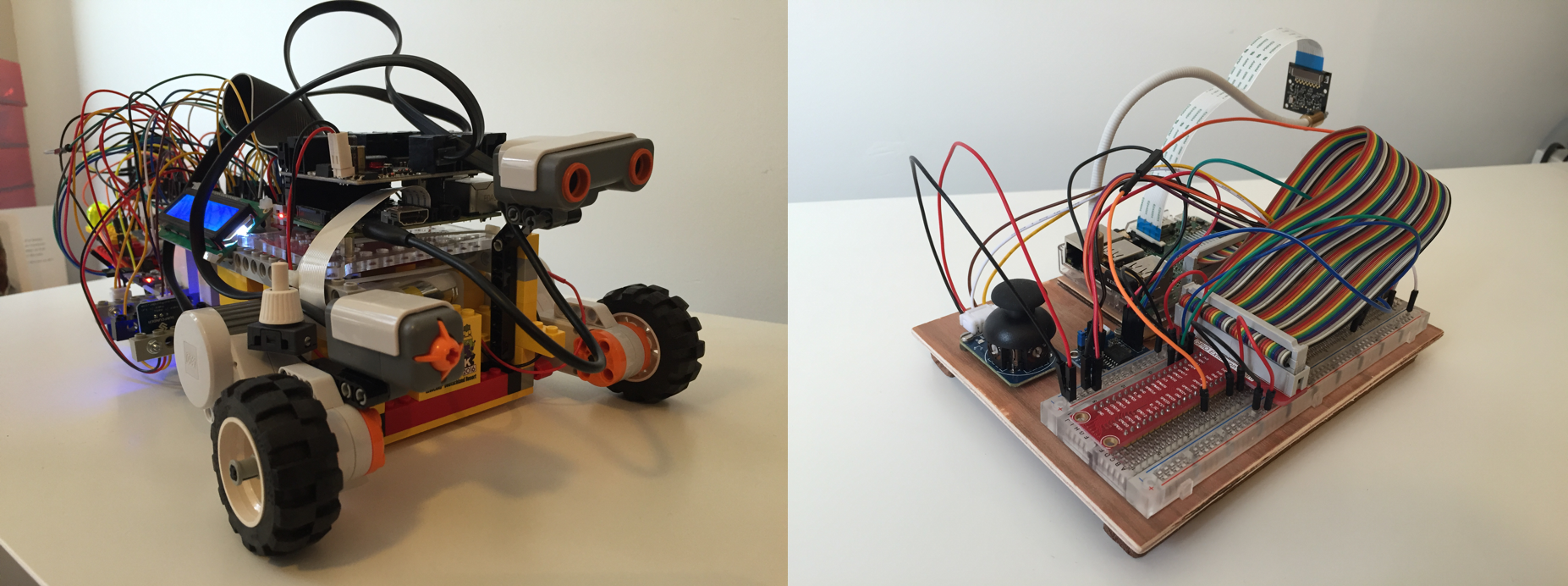
This robot contains a maximum of the components developed in the framework, and is composed of two main parts: the robot (part 1) and a "joystick remote" (part 2).
- The part 1 combines a Raspberry Pi 2, a BrickPi, some LEGO Mindstorms NXT sensors and motors, and a set of additional components.
- The part 2 combines a Raspberry Pi 2 and a joystick.
The operating principle is the following: the joystick part (part 2) of the project is used to control the robot (part 1) through the network, as a remote control.
To do so, part 2 is used to create a WiFi hotspot. Part 1 will automatically connect to this hotspot, so that both sides are part of the same network, and can communicate together.
There are two different modes for the joystick. The first mode controls the movements of the robot (by sending commands to control the two motors) while the second one controls the orientation of the camera support (by sending commands to control the two servomotors composing the camera support - the robot contains a camera support which is able to rotate along x and y axis (horizontally and vertically), via two servomotors).
The communications between the joystick remote and the robot are performed by using a MessageLikeSocketServer on part 1 to deal with commands received from part 2.
From the joystick, it is possible to switch from one mode to another by pressing the green button (visible on the breadboard). When the LED is ON: the movements of the robot are controlled; when the LED is OFF: the camera support is controlled.
Regarding the robot part of this project, it has a lot of sensors and actuators. As you can see, there are a lot of cables, and the complete robot seems really tricky. It is not as complex as one could think. Each component simply requires its little electrical circuit. With about 30 components (sensors, motors and actuators), it is unavoidable to have a lot of electric cables.
To facilitate the assemblies, we decided to mount two breadboard directly on the robot.
The structure of the robot is only made of LEGO building blocks. We just use some screws with nuts and a few colsons to fix the additional components to LEGO Technic building blocks.
The robot is composed of two floors: the first one is used to hold batteries (a power bank for the Raspberry Pi, a 6x1.5V battery holder for the BrickPi and a 4x1.5V battery holder for the servomotors controlling the camera support) and the second one is used for the breadboards, the Raspberry Pi, the BrickPi, etc.
An LCD display is present on the robot. It is used to display some information coming from some sensors such as the thermistor, the photoresistor, etc.
The information shown on the display can be switched by using a simple infrared media remote, via an infrared receiver placed under the LCD display.
We wanted this robot to be as generic as possible to be able to test the components in different use cases. Indeed, combining a thermistor with a camera, an LCD display and a buzzer does not necessarily make sense.
When developing the framework, we tried a lot of electrical components. Among them, we found an almost complete kit of sensors sold by Sunfounder (37 Modules Sensor Kit V2.0 for Raspberry Pi).
The main advantage of this kit is the fact that each sensor/actuator is already soldered on a small PCB.
This avoids having to weld the components by ourselves. In the photos presented after, we can observe some blue LEDs next to some components.
Indeed, sometimes, Sunfounder simply added a LED that lights up when the component is powered.
The complete code regarding the implementation of this proof of concept robot is available in the example part of the Raspoid framework.
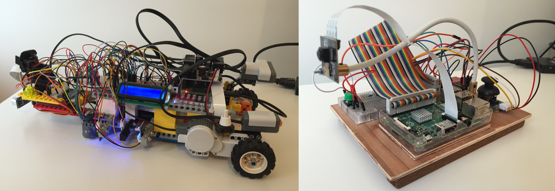
Proof of concept: robot on the left (part 1); joystick remote on the right (part 2).
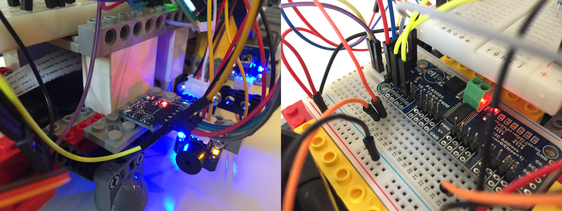
eft part: the MPU6050 and the passive buzzer; Right part: the PCA9685 with 16 PWM output channels.

Left part: BMP180 barometer; Right part: passive buzzer.
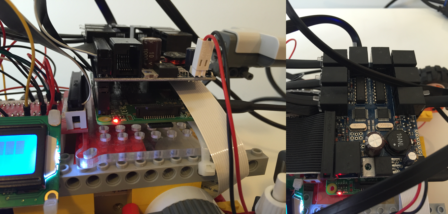
Left part: Raspberry Pi with BrickPi; Right part: BrickPi, from the top.
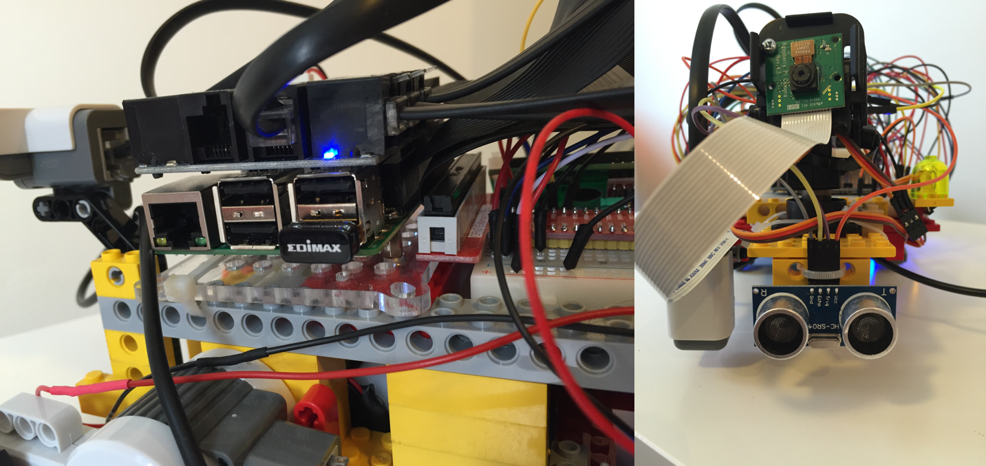
Left part: Raspberry Pi, BrickPi and Edimax WiFi usb key; Right part: camera support, Camera Pi and ultrasonic sensor.
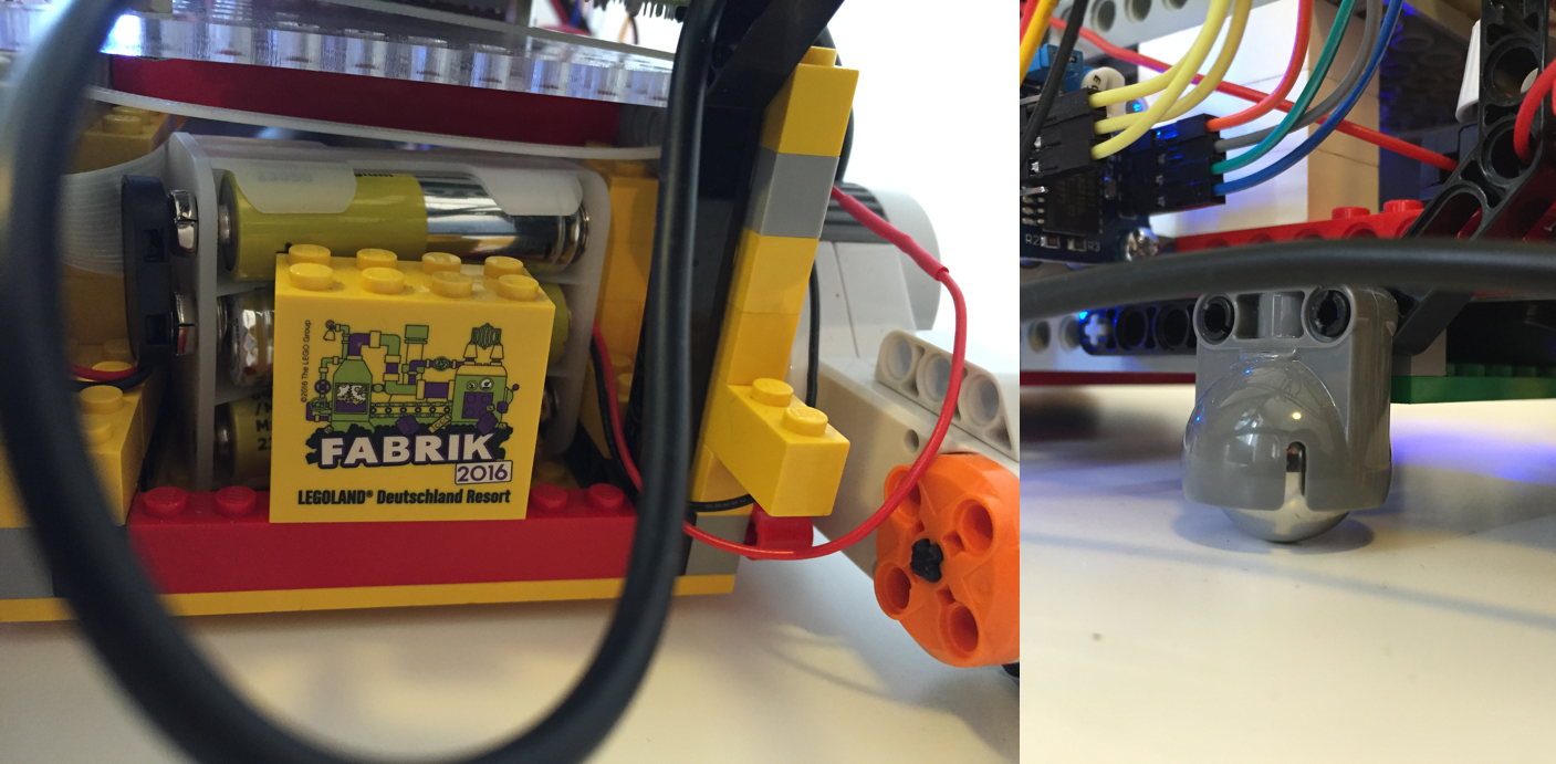
Left part: battery holder for 6x1.5V AA batteries; Right part: LEGO idle wheel.
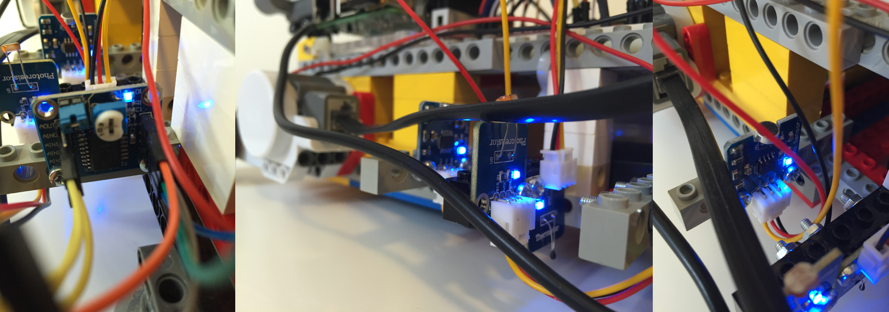
Left part: PCF8591 ADC; Middle part: photoresistor and thermistor; Right part: sound sensor.
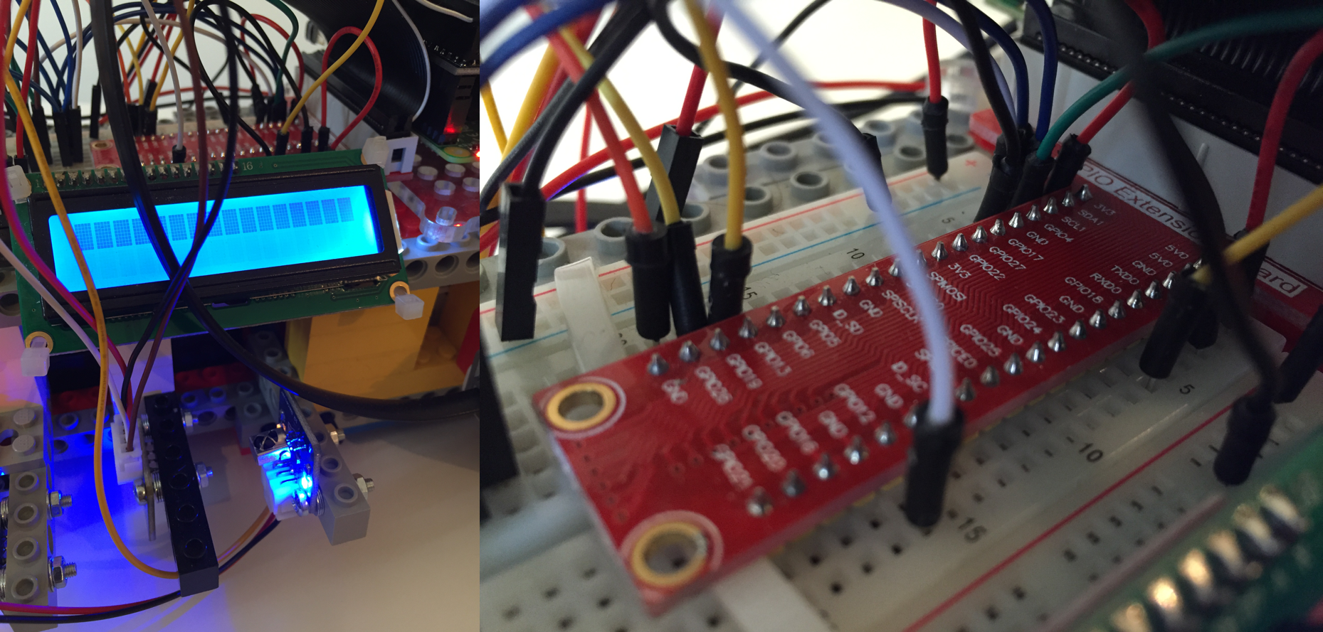
Left part: LCD display and infrared receiver (in the bottom); Right part: a GPIO extension board.
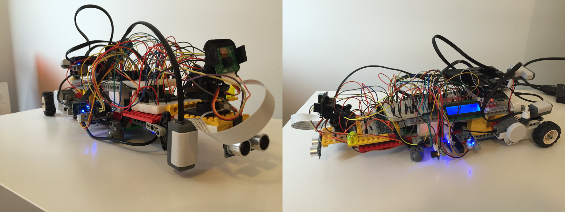
Left part: the robot from the front; Right part: the robot from the top.
Left part: robot from behind; Right part: joystick remote, from the top.